Process control valves
A wide variety of valve types exist, the most widely used for process control systems and other industrial
fluid applications are the valve types which have linear stem and rotary spindle movement:
Linear stem movement type valves include globe valves and slide valves
Rotary spindle type valves include ball valves, butterfly valves, plug valves and their variants
The first choice to be made is between two-port and three-port valves:
Two-port valves ‘throttle’ (restrict) the fluid passing through them
Three-port valves can be used to ‘mix’ or ‘divert’ liquid passing through them
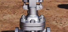
Globe valves are frequently used for control applications because of their suitability for throttling flow and
the ease with which they can be given a specific ‘characteristic’, relating valve opening to flow. For any
given valve orifice size, the greater the differential pressure, the greater the flow rate. The maximum
value of the valve flow coefficient Cv is defined as the number of U.S. gallons of water per minute (at
standard pressure and temperature) that will flow through a wide open valve when there is 1 psig
pressure drop across the valve. The flow rate can be determined by the following equation: 1gpm=Cv√1ΔP
Valve actuators
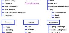
The operation of a control valve involves positioning its movable part (the plug, ball or vane) relative to the stationary seat of the valve. The purpose of the valve actuator is to accurately locate the valve plug in a position dictated by the control signal.
The actuator accepts a signal from the control system and, in response, moves the valve to a fully-open or fully-closed position, or a more open or a more closed position (depending on whether ‘on/off’ or ‘continuous’ control action is used). There are several ways of providing this actuation; the two major ways are by: Pneumatic ActuatorElectric ActuatorOther significant actuators include the hydraulic and the direct acting types. It should be noted that pneumatic actuators do not operate on a standard 3 to 15 psig pressure output from a current to pneumatic convertor (I/P). This is a misconception. The standard pneumatic signal, 3 to 15 psig, is left over from the pneumatic controller days. The actuator operates on 0 to 15 psig or 0 to 30 psig or 0 to 60 psig. The (I/P) may be calibrated from 1.5 to 12.8 psig or 8 to 20 psig to close the valve and overcome the pressure in the pipe pushing up against the valve seat trying to open the valve, as well as any friction of the valve stem packing trying to stop the valve stem from moving. This is called the bench set calibration of the valve’s actuator.
Bryon Lewis, PE, CMfgE, CCNA
![]() Call Us Now
Call Us Now
+84 396992390


 Visit Today : 33
 Visit Yesterday : 44
 This Month : 1045
 This Year : 7555
 Total Visit : 10160
 Hits Today : 51
 Total Hits : 40041
 Who's Online : 1